| |
Isola MT40 2-Layer 0.254mm Immersion Silver High Speed Digital & RF PCB
1. Introduction to Isola MT40 High Speed Digital & RF PCB
The Isola I-Tera MT40 laminate is suitable for many of today's high speed digital and RF/microwave printed circuit designs. I-Tera MT40 features a dielectric constant (Dk) that is stable between -55°C and +125°C up to W-band frequencies. In addition, I-Tera MT40 offers a low dissipation factor (Df) of 0.0031 making it a cost effective alternative to PTFE and other commercial microwave and high-speed digital laminate materials.
I-Tera MT40 laminate materials are currently being offered in both laminate and prepreg form in typical thicknesses and standard panel sizes. This provides a complete materials solution package for high-speed digital multilayer, hybrid, RF/microwave, multilayer and double-sided printed circuit designs. I-Tera MT40 does not require any special through hole treatments commonly needed when processing PTFE-based laminate materials.
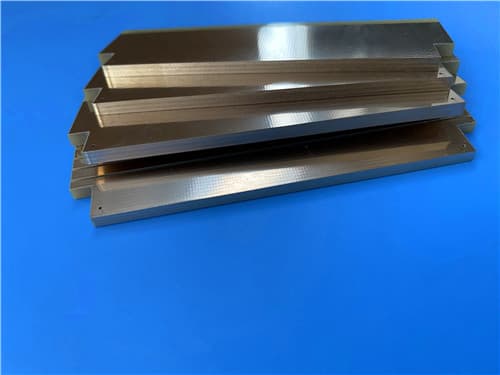
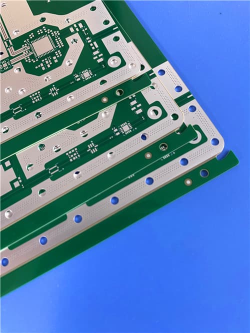
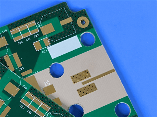
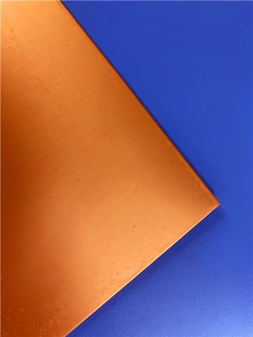
This 2-layer rigid PCB is constructed entirely with MT40 as the core material at 0.254mm (10mil) thickness, with immersion silver surface finish, white top silkscreen, no solder mask, and 1oz copper on both sides. Its stable DK of 3.45 offers excellent high-frequency performance, making it ideal for demanding applications such as high speed digital, RF/microwave, multilayer and double-sided printed circuit designs.
2. Key Features
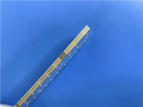
Dielectric Constant (DK): 3.45 @ 2GHz Dissipation Factor (Df): 0.0031 @ 2GHz Glass Transition Temperature (Tg): 215°C (DSC), 230°C (DMA), 210°C (TMA) Decomposition Temperature (Td): 360°C @ 5% weight loss Z-Axis CTE: 55 ppm/°C (Pre-Tg), 290 ppm/°C (Post-Tg) X/Y-Axis CTE: 12 ppm/°C (Pre-Tg) Thermal Conductivity: 0.61 W/m·K Immersion Silver surface finish White top silkscreen, no solder mask Board dimensions: 108mm x 35mm = 1PCS Metal edge wrapping at designated positions RoHS Compliant, CAF resistant Lead-free assembly compatible, FR-4 process compatible
3. Benefits
Stable DK (3.45) — Consistent impedance control for high-speed digital and RF designs Low Df (0.0031) — Excellent high-frequency performance with minimal signal loss High Tg (215°C) — Excellent thermal reliability for lead-free assembly No special through hole treatments required — Simplified processing compared to PTFE materials FR-4 Process Compatible — Standard PCB fabrication processes can be used RoHS Compliant & CAF Resistant — Environmentally friendly and reliable Multiple reflow and lamination cycles capable — Suitable for complex multilayer designs Immersion Silver Finish — Excellent solderability, corrosion resistance, and electrical performance
4. PCB Construction Details
| Item | Specification |
|---|
| Base material | Isola I-Tera MT40 (Thermoset Laminate) |
| Layer count | 2-layer rigid PCB |
| Board dimensions | 108mm x 35mm = 1 PCS |
| Minimum Trace/Space | Specified by design |
| Minimum Hole Size | Specified by design |
| Blind vias | No |
| Finished board thickness | 0.254mm (10mil) core + copper |
| Finished Cu weight | 1 oz (35 μm / 1.4 mils) all layers |
| Via plating thickness | Standard |
| Surface finish | Immersion Silver |
| Top Solder Mask | No |
| Bottom Solder Mask | No |
| Top Silkscreen | White |
| Bottom Silkscreen | No |
| Metal Edge Wrapping | At designated positions |
| Quality standard | IPC-Class-2 |
| 100% Electrical test | Used prior to shipment |
5. PCB Stackup (2-Layer Rigid Structure)
Layer 1 (Top Copper) – 35 μm (1 oz)
Isola MT40 Substrate – 0.254 mm (10mil)
Layer 2 (Bottom Copper) – 35 μm (1 oz)
6. Isola I-Tera MT40 Material – Product Introduction
Thermal Performance
Tg: 215°C (DSC), 230°C (DMA), 210°C (TMA)
Td: 360°C @ 5% weight loss
Electrical Performance
Dk: 3.45 @ 2GHz
Df: 0.0031 @ 2GHz
I-Tera MT40 is suitable for many of today's high speed digital and RF/microwave printed circuit designs. I-Tera MT40 features a dielectric constant (Dk) that is stable between -55°C and +125°C up to W-band frequencies. In addition, I-Tera MT40 offers a lower dissipation factor (Df) of 0.0031 making it a cost effective alternative to PTFE and other commercial microwave and high-speed digital laminate materials.
I-Tera MT40 laminate materials are currently being offered in both laminate and prepreg form in typical thicknesses and standard panel sizes. This provides a complete materials solution package for high-speed digital multilayer, hybrid, RF/microwave, multilayer and double-sided printed circuit designs. I-Tera MT40 does not require any special through hole treatments commonly needed when processing PTFE-based laminate materials.
Product Features:
• RoHS Compliant
• CAF resistant
• Lead-free assembly compatible
• FR-4 process compatible
• Multiple reflow capable
• Multiple lamination cycles
• Currently manufactured in Asia, North America, Europe
Product Availability:
• Standard Laminate: 2 to 24 mil (0.05 to 0.61 mm)
• Copper Foil types: HVLP (VLP2) ≤2.5 micron Rz JIS, RTF (Reverse Treat Foil), Embedded resistor foil
• Copper weight: 0.5, 1 and 2 oz (18, 35 and 70 μm) available; heavier and thinner available
• Prepreg available with tooling and moisture barrier packaging
• Glass Fabric: E-glass, Square weave glass, Mechanically spread glass
7. Features and Benefits Summary
| Feature | Benefit |
|---|
| DK 3.45 @ 2GHz | Stable dielectric constant for consistent impedance control |
| Df 0.0031 @ 2GHz | Low loss for high-speed digital and RF/microwave designs |
| Tg: 215°C | Excellent thermal reliability for lead-free assembly |
| No special through hole treatments required | Simplified processing compared to PTFE materials |
| FR-4 process compatible | Standard PCB fabrication processes can be used |
| RoHS Compliant & CAF Resistant | Environmentally friendly and reliable |
| Multiple reflow and lamination cycles | Suitable for complex multilayer designs |
| Immersion Silver finish | Excellent solderability, corrosion resistance, electrical performance |
8. Isola I-Tera MT40 Typical Properties (Data Sheet)
| Property | Typical Value | Unit | Test Method (IPC-TM-650 or as noted) |
|---|
| Thermal Properties |
| Glass Transition Temperature (Tg) by DSC | 215 | °C | 2.4.25C |
| Glass Transition Temperature (Tg) by DMA | 230 | °C | 2.4.24.4 |
| Glass Transition Temperature (Tg) by TMA | 210 | °C | 2.4.24C |
| Decomposition Temperature (Td) @ 5% weight loss | 360 | °C | 2.4.24.6 |
| Time to Delaminate (T260) | >60 | Minutes | 2.4.24.1 |
| Z-Axis CTE (Pre-Tg) | 55 | ppm/°C | 2.4.24C |
| Z-Axis CTE (Post-Tg) | 290 | ppm/°C | 2.4.24C |
| Z-Axis CTE (50-260°C Total Expansion) | 2.8 | % | 2.4.24C |
| X/Y-Axis CTE (Pre-Tg) | 12 | ppm/°C | 2.4.24C |
| Thermal Conductivity | 0.61 | W/m·K | ASTM E1952 |
| Thermal Stress 10 sec @ 288°C (Unetched) | Pass | Visual | 2.4.13.1 |
| Electrical Properties |
| Dk @ 2 GHz | 3.45 | — | 2.5.5.5 |
| Df @ 2 GHz | 0.0031 | — | Bereskin Stripline |
| Volume Resistivity (C-96/35/90) | 1.33 x 10⁷ | MΩ-cm | 2.5.17.1 |
| Surface Resistivity (C-96/35/90) | 1.33 x 10⁵ | MΩ | 2.5.17.1 |
| Dielectric Breakdown | 45.4 | kV | 2.5.6B |
| Arc Resistance | 139 | Seconds | 2.5.1B |
| Electric Strength | 45 (1133) | kV/mm (V/mil) | 2.5.6.2A |
| Comparative Tracking Index (CTI) | 3 | Class | UL 746A / ASTM D3638 |
| Mechanical & Physical Properties |
| Peel Strength (1 oz. EDC foil) | 1.0 (5.7) | N/mm (lb/inch) | 2.4.8C |
| Flexural Strength (Length direction) | 490 (71.0) | MPa (kpsi) | 2.4.4B |
| Flexural Strength (Cross direction) | 400 (58.0) | MPa (kpsi) | 2.4.4B |
| Tensile Strength (Length direction) | 269 (39.0) | MPa (kpsi) | ASTM D3039 |
| Tensile Strength (Cross direction) | 241 (35.0) | MPa (kpsi) | ASTM D3039 |
| Young's Modulus (Length direction) | 3060 | ksi | ASTM D790-15e2 |
| Young's Modulus (Cross direction) | 2784 | ksi | ASTM D790-15e2 |
| Poisson's Ratio (Length direction) | 0.234 | — | ASTM D3039 |
| Poisson's Ratio (Cross direction) | 0.222 | — | ASTM D3039 |
| Moisture Absorption | 0.1 | % | 2.6.2.1A |
| Flammability | V-0 | Rating | UL 94 |
| Relative Thermal Index (RTI) | 130 | °C | UL 796 |
9. Primary Application Areas
High speed digital printed circuit designs RF and microwave circuitry Multilayer and hybrid printed circuit designs Double-sided printed circuit designs Telecommunications and networking equipment Aerospace and defense applications Test and measurement equipment
10. Quality Assurance
Type of artwork supplied: Gerber RS-274-X Accepted standard: IPC-Class-2 Availability: Worldwide 100% Electrical test prior to shipment Metal edge wrapping at designated positions
11. Standard Thickness, Panel Sizes & Claddings
| Parameter | Options |
|---|
| Standard Laminate Thicknesses | 2 to 24 mil (0.05 to 0.61 mm) |
| Copper Foil Types | HVLP (VLP2) ≤2.5 micron Rz JIS, RTF (Reverse Treat Foil), Embedded resistor foil |
| Copper Weight | 0.5, 1 and 2 oz (18, 35 and 70 μm) available; heavier and thinner available |
| Prepreg | Tooling of prepreg panels, moisture barrier packaging |
| Glass Fabric | E-glass, Square weave glass, Mechanically spread glass |
12. Data Source Notes
Dielectric Constant is tested in the Z-direction of the material using IPC-TM-650 2.5.5.5 Stripline method. All test data are typical measurement values intended to assist customers in material selection. They do not constitute any express or implied warranty and do not guarantee performance in specific applications. Customers are responsible for verifying the suitability of Isola materials for each application. I-Tera MT40 is manufactured in Asia, North America, and Europe.
|
|